| |
|
|
 |
 |
|
TRANSPACE offers a proven, timely and economical solution to work overloads and technical problems and has participated in many major Indian military defense and aerospace programs. TRANSPACE has the expertise and experience to perform engineering analysis tasks. |
|
| |
Transpace's meticulous analysis helps find and eliminate design flaws before they reach production. Our years of experience in all forms of circuit analysis enable us to quickly fulfill your projects' needs and satisfy your most exacting customers.
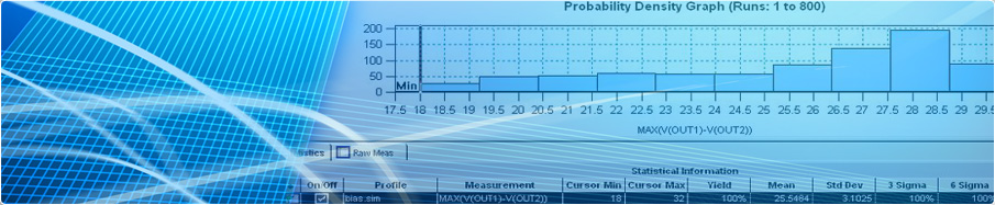
A Worst Case Circuit Analysis is a quantitative assessment of the equipment performance, accounting for manufacturing, environmental and aging effects. In addition to a circuit analysis, a WCCA often includes stress and derating analysis, Failure Mode Effects and Criticality Analysis (FMECA) and Reliability Prediction (MTBF) The specific objective is to verify that the design is robust enough to provide operation which meets the system performance specification over design life under worst case conditions and tolerances (initial, aging, radiation, temperature, etc.).
The Stress and Derating Analysis is intended to increase reliability by providing sufficient margin compared to the allowable stress limits. This reduces overstress conditions that may induce failure, and reduces the rate of stress-induced parameter change over life. It determines the maximum applied stress to each component in the system.
WCCA is not a candidate for elimination when there are cost overruns.
When a WCCA is performed properly, the results often save companies millions of dollars in lost revenue, dramatically lessen the possibility of human disaster, and avert potential disasters both monetary and political.
Conducting a WCCA during the design phase should be a top consideration. The typical cost of performing a rigorous WCCA is generally less than 1% of the program cost. The cost of not doing the WCCA can cost 100% of the program cost.
We have seen many program failures, which required at the least, major redesigns AFTER completion of qualification testing. This costs enormous amounts of time and money.
Can't electrical testing be used as a less expensive an alternative? The answer is generally "No". Testing normally only determines Beginning of Life (BOL) performance. In many cases extended testing needs to be performed with extreme operating conditions such as temperature, voltage, power, etc. in order to determine End-Of-Life (EOL) margins. This can overstress the hardware. Testing is only valid for the measured lot and may vary lot-to-lot and manufacturer-to-manufacturer. It requires the parts to be procured PRIOR to completion of the WCCA, which can be Very RISKY!! And it can be very costly if many measurements are required. |
| |
| The WCCA is recommended for the following areas |
- Aerospace Weapons and Satellites
- Nuclear Reactors
- Medical Electronics
- Transportation Systems
|
- Oceanics
- Ammunition Production Facilities
- Naval Systems and Ship Board Equipments
- Test equipment and facilities
|
|
| Benefits From WCCA |
- Assure acceptable operation throughout the entire product life cycle under the
most unfavorable combination of anticipated conditions [Worst Case
Extreme Value Analysis (EVA)]
- Define Critical Components and Spec. Control Drawing (SCD) Limits
- Provide Acceptance Test Procedure (ATP) Limits
|
- Define Need for and Range of Select-At-Test (SAT) components
- Improve Reliability through Parts Stress and Derating analysis
- Identify design concerns, which during test, alignment, and use could result in circuit damage or premature degradation.
|
|
| |
| Top |
Factors Addressed During WCCA :
- Analog Circuit Analysis: Some of the factors to be considered during analysis include
|
| |
 |
|
- Maximum line voltage variations and line transients
- Maximum input and output variation
- Maximum part parameter variation
- Maximum performance demands and variations
- Maximum and minimum environmental conditions
|
|
- Fail-safe provisions
- Redundancy provisions
- Radiation effects, as applicable
- Parameter drift due to aging
|
- Transients due to turn-on, turn-off, and state changes
- Fatigue due to cyclical loading and temperature cycling
- Interface conditions between modules and modules to test equipment
|
|
| |
| Top |
Digital Circuit Analysis:
- Digital circuit worst case analyses involves one or more of the following:
|
 |
|
- Timing Margin Analysis
- Transmission Line Effects
- Noise Due to Cross-talk and Grounding
- Meta-Stability Analysis
- Decoupling Analysis
|
|
- Fan-out Analysis
- Logic Compatibility/Interface Analysis
- Supply Power Application and Sequencing Analysis.
- State Machine Analysis
- Unused/Tri-stated Input Analysis
|
- No Connection Analysis
- Test Point Current Limiter Analysis
- Physical Layout Analysis
- One-Shot Margin Analysis
|
|
| Component Tolerances |
- Initial
- Temperature and Environmental Factors
|
- Radiation
- Aging or End-of-Life Factors
|
|
| |
| Top |
 |
 |
|
This analysis Minimizes possibility of catastrophic piece part failures. This task assures that no electrical/electronic piece parts will be overstressed and that all parts are properly derated in general accordance with military practices. |
|
| |
A stress and Derating analysis is a detailed percentage accounting of the applicable Voltage, Current and Power stress on each individual element within a device or system with regards to the component rating. Most failures in a device or system are a direct result of overstress of the element compared with its rating. This analysis is typically performed by hand, and summarized in a spreadsheet format. SPICE models or other mathematical models may be used to determine the applicable stress.
Interface Analysis:
An interface analysis assures that each interface meets the output and input requirements to perform a given function. In digital circuits, a good example is to assure that TTL outputs are joined with TTL compatible inputs, and that the fans out requirements are met. This also applies to some analog functions. As an example an interface analysis might be used to assure that a MOSFET switch is fully enhanced and also fully depleted in order to assure full circuit performance.
|
| |
| Top |
 |
| This analysis looks at the failure of each element within a device or system to determine the effect on the end performance. The failure of an element may be simple or complex. As an example, a resistor has three failure modes. The resistor could be open, shorted or outside of its specified tolerance. An integrated circuit is obviously much more complex. The goal is to eliminate any single point failures that would cause the device or system to fail to meet its performance requirements. Another way to look at this is to assure graceful degradation of a device or system. As a further example, suppose that the input to a device or system is couple to the outside world, via a resistor. If the resistor were to open, there would be no output from the device or system. The effect is therefore non-performance, the criticality is very high, and this constitutes a single point failure. The goal is to minimize the likelihood of single point failures and to provide the greatest amount of graceful degradation. |
| |
| Top |

Single Event Upset (SEU) Analysis
Single Event Upset (SEU) is a change of state or transient induced by an ionizing particle such as a cosmic ray or proton (Heavy Ion) in a device. This may occur in digital, analog, and optical components or may have effects in surrounding circuitry. These are "soft" bit errors in that a reset or rewriting of the device causes normal behavior thereafter. A full SEU analysis considers the system effects of an upset. For example, a single bit flip, while not damaging to the circuitry involved, may damage the subsystem or system (i.e., initiating a pyrotechnic event).
Soft Errors
SEU - Single Event Upset occurs when a device changes state transiently and can be readily reset.
MBU - Multiple Bit Upset occurs when a single radiation event causes upset to more than one element of the device.
Hard Errors may be non-destructive or destructive
SEL - Single Event Latch-up, a current path is established, and while powered the state of that node cannot be changed. When the current flow is large enough, the device may be permanently damaged.
SEB - The penetration of the source-body-drain region of a high voltage device by the charge deposited by a heavy ion or neutron-induced recoil can forward bias the body region, so that if the terminal bias applied to the drain exceeds the local breakdown voltage, the resulting pulse can initiate avalanching, leading to destructive burnout.
SEFI - Single Event Functional Interrupt, refers to an SEU in a complex device e.g. microprocessor whereby a control path is corrupted with the result that the part ceases to function properly
We analyze the circuit behavior for the SEU conditions and suggest the mitigation techniques based on the effects analyzed with the respective components and circuits.
Single Event Transient (SET) Analysis
A Single Event Transient (SET), also known as an Analog Single Event Upset (ASEU), in a linear device, is caused by the generation of charge by single particle (proton or heavy ion) passing through a sensitive node in the linear circuit. The SET consists of a transient voltage pulse generated at that node that propagates to the device output.
SET analysis for the component types mentioned below are required to be done:
- OPAMPs
- Comparators
- Regulators / Voltage References
- PWMs
- PLL
- Digital Optocouplers
We analyze the circuit behavior for the transient conditions of Single event transients and suggest the mitigation techniques based on the effects analyzed with the respective circuit diagrams and simulation plots. |
| |
| Top |
|
|